A phase-locked loop (PLL) is an electronic circuit that controls
an oscillator so that it maintains a constant phase angle relative
to a reference signal. In communications, the oscillator is usually
at the receiver, and the reference signal is extracted from the
signal received from the remote transmitter. Phase-locked loops
are widely used in space communications for coherent carrier
tracking and threshold extension, bit synchronization, and symbol
synchronization.
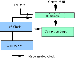
A Digital PLL (DPLL) circuit may consist of a serial shift register which receives digital input samples (extracted from the received signal), a stable local clock signal which supplies clock pulses to the shift register to drive it and a phase corrector circuit which takes the local clock and regenerates a stable clock in phase with the received signal by slowly adjusting the phase of the phase of the regenerated clock to match the received signal.

The adjustment is performed by correction logic based on a high-speed sample of each bit (at eight times the bit rate in the figure below). To illustrate this, if the sampled signal shows a single transition at the centre of the bit, the clock is already aligned. If the transition appears to the right of centre, the clock period is too long, and the frequency is increased. If the transition appears to the left, the period must be too short, so the frequency is decreased. Not all waveforms generate a transition for each bit, if there are no transitions the circuit does not perform correction. This is decribed more in the following section.

Simplified phase-locked loop
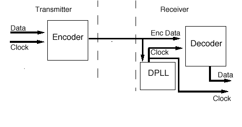
This circuit is useful when the data and clock are sent together over a common cable (as in Manchester encoding), since it allows the receiver to separate (regenerate) the clock signal from the received data. The regenerated clock signal is then used to sample the received data and determine the value of each received bit.

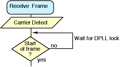
When a signal is first received, the regenerated clock and the received signal will not be aligned. (This happens at the start of an Ethernet frame, since the receiver has no knowledge of which transmitter sent the frame, and therefore the frequency and phase of the received clock signal). The loop starts to track the received signal, and eventually locks-in to the required signal, allowing it to find the center of each received data bit, and reliably decode the received information. Knowing that this process takes time, many systems (including Ethernet) employ a preamble which contains a well-known and simple data pattern which increases the speed at which the DPLL gains lock of the clock signal.
There are many designs of phase locked-loop circuit, but the basics of operation is similar in each case. The received signal is sampled at the local clock speed (which is a multiple of the nominal regenerated clock frequency, e.g. 8 or 32 times). Each sample (0 or 1) is placed in the shift register. The need to adjust the phase is detected by viewing set of samples of the received signal. At each regenerated bit period, the register is consulted. If the center of the received bit lies at the center of the shift register, the two clocks are in phase. If the regenerated clock signal lags the reference signal, then the phase adjuster needs to compensate for this by advancing the regenerated clock. If it leads the reference signal, the phase adjuster needs to make the opposite change.
Since Manchester encoding always contains a bit transition (0-1, or 1-0) at the center of each bit, the shift register (using a 32x local clock) should contain either the value:
00000000000000001111111111111111 (if a 1 was sent and the clocks were locked)
or
11111111111111110000000000000000 (if a 0 was sent and the clocks were locked) .
The shift register contains the pattern 11111000000000000000011111111111 if the regenerated clock is out of alignment with the received data by 5 local clock frequency periods.
The transitions at the centre of each bit makes locking onto a Manchester encoded signal particularly easy. Another method to introduce clock-transitions into the data is to use 4b/5b or 8b/10b encoding as in Fast Ethernet and Gigabit Ethernet over twisted pair cables.
By updating the phase-adjuster each received bit period, the frequency of the regenerated clock can be precisely aligned to the required reference.When a difference is found, the regenerated clock is normally advanced only a small amount each time the shift register is read, thus a number of received bit periods are required to compensate for a large difference in the two clocks. The larger the difference the longer it takes for the loop to set the desired frequency of the regenerated clock. Once the loop has found the desired regenerated clock frequency, only small changes are required to keep the clock aligned to the received data.
An important aspect of using this circuit, is that once the phase locked loop has found the desired frequency, noise in the received signal causes only very small (random) changes in the input clock - the regenerated clock continues to provide a good reference that may be used to find the center of each received bit.

A node starts transmission by sending an 8 byte (64 bit) preamble sequence. This consists of 62 alternating 1’s and 0’s followed by the pattern 11. Strictly speaking the last byte which finished with the ‘11’ is known as the “Start of Frame Delimiter”. When encoded using Manchester encoding, at 10 Mbps, the 62 alternating bits produce a 5 MHz square wave.
The purpose of the preamble is to allow time for the receiver in each node to achieve lock of the receiver Digital Phase Lock Loop which is used to synchronise the receive data clock to the transmit data clock. At the point when the first bit of the preamble is received, each receiver may be in an arbitrary state (i.e. have an arbitrary phase for its local clock). During the course of the preamble it learns the correct phase, but in so doing it may miss (or gain) a number of bits. A special pattern (11), is therefore used to mark the last two bits of the preamble (resulting in a rapid transistion). Strictly speaking the last byte which finished with the ‘11’ is known as the “Start of Frame Delimiter”. When this is received, the Ethernet receive interface starts collecting the bits into bytes for processing by the MAC layer.