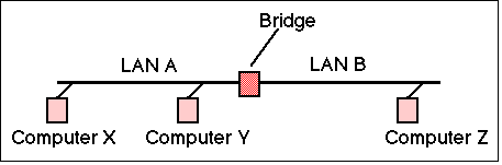
A Bridge or Switch is a LAN interconnection device that operates at the link layer (Layer 2). It can be used to join two LAN segments (A,B), constructing a larger LAN. Bridges were first specified in IEEE 802.1D (1990) and later by ISO (in 1993).
The MAC protocol is responsible for access to the medium and for the diagnosis of failure in either the medium or the transceiver which attaches to the medium. The format of an Ethernet frame (also known as MAC - Medium Access Control) consists of two 6 byte addresses and a one byte protocol ID / length field. The destination address field allows a frame to be sent to single and groups of destination interfaces.
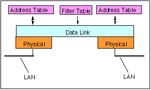
A bridge forwards (receives and then transmits) frames from one LAN (e.g. LAN A in the figure below) to another (e.g. LAN B). Obviously, the bridge could forward all frames, this would behave rather like a repeater; however a transparent bridge is much smarter, becasue it only forwards frames that need to travel from one LAN to another. The bridge address table controls which packets are forwarded and which are not, based on the destination MAC address in each received frame and the contents of the address table.
Although a bridge could be configured to setup simplest type of bridge, and that most frequently used is the Transparent Bridge. This type of bridge requires no configuration (users of the LAN are unaware of its presence). To work transpaerently, a bridge need to learn which computers are connected to which of its LAN interfaces. More formally, it need to learn the set of source address that are received on each interface. The source address of each received frame is recorded in the address table, together with the port on which the frame was received. This is called learning. In the figure, consider three computers X,Y,Z. Assume each sends frames to the other computers. The source addresses X and Y are observed to be on network A, while the address of computer Z will be observed to be on network B.
The learned source addresses are stored in the an interface address table, associated with the corresponding port (interface) in which the address was received. Once this table has been created, the bridge can use the information to match the destination address of each received frame. The bridge scans the interface tables to see if a frame's destination address matches an entry.
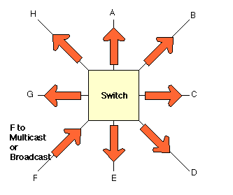
Three possibilities exist:
Frames with a source address of X and destination address of Y are received and discarded, since in this case the computer Y is directly connected to the LAN A, whereas frames sent from X with a destination of Z are forwarded to network B by the bridge.
Bridges forward a broadcast frame to all connected ports, except the port on which the frame was received.
The normal action for forwarding a multicast frame is to treat them the same as a broadcast frame. This is clearly suboptimal, since a bridge may send multicast frames to parts of the network for which there are no interested receivers. Some bridges implement extra processing to control the flooding of multicast frames.
A bridge can use many design to implement an interface addresss table. This could use a software data structure or use a Contents Addressable Memory (CAM) chip. In either case, the size of the table is finite, and usually constrained to 1000's - 10 000's of entries. To help keep the table small, most bridges maintain a check of how recently each dynamically-learned source address was used. Addresses that have not been used for a long period of time (e.g. minutes) are deleted. This has the effect of removing unused entries, but if the address happens to be used again before a frame is received from the same source address, it will require the frame to be flooded to all ports. This reduces efficiency of tranmission, but does not result in loss.
A useful side effect of deleting old addresses is that the bridge interface table records only working MAC addresses. If an Ethernet Interface stops sending, its address will then be deleted from the table. If the interface is subsequently reconnected, the entry will be restored, but if the connection is made to another port (the cable is changed) a different (updated) entry will be inserted corresponding to the actual port associated with the address. (The bridge always updates the interface table for each source address in a received MAC frame, therefore even if a computer changes the point at which it is connected without first having the address table entry removed, the bridge will still update the table entry).
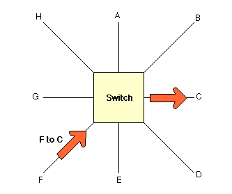
A bridge with more than two interfaces (ports) is also known as a switch. There are important differences between brdiges/switches and hubs. In particular, the way in which they forward frames.
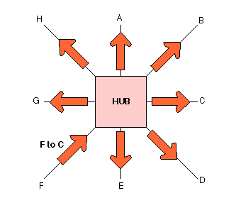
A hub (or repeater) forwards a received frame to all the output interfaces (ports), resulting in the frame reaching all connected equipment in the collision domain, even though a unicast frame will be only destined for a system connected to one of the interfaces (C, in the above diagram).
Once an address is learned, a switch forwards a frame to only the required interface/port. By sending the frames only to parts of the network where it need to go, the switch reduces the number of frame that need to be sent on the other LAN segments (and hence the load on these segments), increasing the overall performance of the connected LANs. The switch also improves security, since frames only travel where they are intended (and can not in this case, for instance, be observed by an unauthorised computer attached to segment A).
Switches (like bridges) normally forward all multicast and broadcast frames to all the receivers.
Some switches have extra processing to help improve performance of multicast forwarding.
More details about this, and the operation of switches may be found in a related page (see below).
Note:
Bridges receive Ethernet frames using a port set to the promiscuous mode, and hence see all frames that are sent over the LAN. the decide whether to forward the frames that they receive based on the Ethernet MAC destination address of a received frame. This results in reduced traffic on other ports, since traffic is only forwarded when it has to be.
Bridges can be unmanaged or managed. Most cheap consumer bridges are unamnaged. They are simply plug and play, and do not require any configuration. Most enterprise bridges are managed. They allow the network operator to configure the bridge and determine which interfaces can be used. A managed bridge can be used to set static entries in the address table to configure an association between an address and a specific port.
In some managed bridges, a system administrator may override the normal forwarding by inserting entries in a filter table to inhibit forwarding between different work groups (for example to provide security for a particular set of MAC addresses). This may enforce a security policy separating different work groups located on each of the LAN interaces. Filters are typically set based on some combination of the source address, destination address, or interface port. Frames that match entries in the filter table will only be forwarded to specific configured ports. This can be used to implement security polcies and also to constrcut Virtual LANs. This could be used, for instance to permit only Etherenet Interaces with a specific MAC address to be connected to a specific port, or to allow only frames with specific source address to be forwarded to a specific set of MAC addresses.
There is a rule controlling the interconnection of bridges and switches (as there is for Ethernet Hubs). The rule says simply, that a bridge / switch /hub must not be connected to form a tree or a ring. That is, there must be only one path between any two Ethernet Interfaces. If more than one parallel path were to exist, a loop would be formed, resulting in endless circulation of frames over the loop. This would soon result in overload of the network.
IEEE (in IEEE 802.1D) has defined the Spanning Tree Algorithm (STA) that automatically detects loops and disables all but one of the parallel paths.