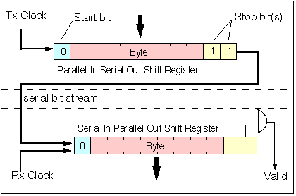
The asynchronous communication technique is a transmission technique which is most widely used by personal computers to provide connectivity to printers, modems, fax machines, etc. This allows a series of bytes (or ASCII characters) to be sent along a single wire (actually a ground wire is required to complete the circuit). The data is sent as a series of bits. A shift register (in either hardware or software) is used to serialise each information byte into the series of bits which are then sent on the wire using an I/O port and a bus driver to connect to the cable.
At the receiver, the remote system reassembles the series of bits to form a byte and forwards the frame for processing by the link layer. A clock (timing signal) is needed to identify the boundaries between the bits (in practice it is preferable to identify the centre of the bit - since this usually indicates the point of maximum signal power). There are two systems used to providing timing:
The principle difference between the synchronous and asynchronous modes of transmission is that in the synchronous case, the receiver uses a clock which is synchronised to the transmitter clock. Synchronous transmission has the advantage that the timing information is accurately aligned to the received data, allowing operation at much higher data rates. It also has the advantage that the receiver tracks any clock drift which may arise (for instance due to temperature variation). The penalty is however a more complex interface design, and potentially a more difficult interface to configure (since there are many more interface options). Most computers support asynchronous communication, not all computers support synchronous serial communication. The most significant aspect of asynchronous communications is that the transmitter and receiver clock are independent and are not synchronised. In fact, there need be no timing relationship between successive characters (or bytes of data). Individual characters may be separated by any arbitrary idle period.

An asynchronous link communicates data as a series of characters of fixed size and format. Each character (usually represented by an ASCII code) is preceded by a start bit and followed by 1-2 stop bits. Parity is often added to provide some limited protection against errors occurring on the link. The use of independent transmit and receive clocks constrains transmission to relatively short characters (<8 bits) and moderate data rates (< 64 kbps, but typically lower). The asynchronous transmitter delimits each character by a start sequence and a stop sequence. The start bit (0), data (usually 8 bits plus parity) and stop bit(s) (1) are transmitted using a shift register clocked at the nominal data rate.

At the receiver, a clock of the same nominal frequency is constructed and used to clock-in the data to the receive shift register. Only data that are bounded by the correct start and stop bits are accepted. This operation is normally performed using a UART (Universal Asynchronous Receiver Transmitter). UART chips are available as Integrated Circuits (ICs) or may form a part of a more complex component. Some CPUs include UARTs as a standard feature.
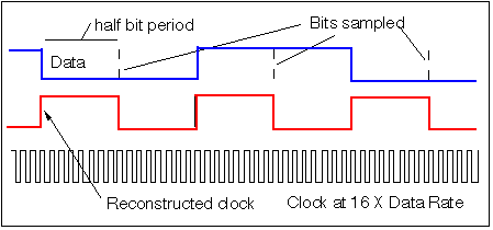
The receiver is started by detecting the edge of the first start bit as shown below:

The reconstructed receive clock (receive (rx) clock) is normally generated using a local stable high rate clock, frequently operating at 16 or 32 times the intended data rate. Such a clock signal (square wave signal) may be created using a crystal oscillator circuit. In most cases, the computer will already have a square wave clock generator (e.g. connected to the clock input of the CPU), and rather than using a separate clock, this clock signal may be routed to the UART. In general, whatever method is used, the clock will be of too high a frequency for the UART, the clock frequency may however be easily reduced using a succession of frequency dividers (each a flip-flop wired to divide the input clock by 2).
Reception proceeds by detecting the edge of the start bit and counting sufficient clock cycle from the high frequency clock (16 times the transmission clock in the example here) to identify the mid position of the start bit. The number of bits to be converted is the number corresponding to one half the original bit period, 8 high frequency clock cycles in this example). From there the centre of the successive bits are located by counting cycles corresponding to the original data speed (16 in this example).

Asynchronous serial links may be used to connect computers via modems to an Internet Service Provfider (ISP). When asynchronous transmission is used to support packet data links (e.g. the Internet), then special characters have to be used ("framing") to indicate the start and end of each frame transmitted. One character (known as an escape character) is reserved to mark any occurrence of the special characters within the frame. In this way the receiver is able to identify which characters are part of the frame and which are part of the "framing". Packet communication over asynchronous links is used by most home users to get access to a network using a modem. The set of rules governing what sequence of characters are sent is known as the Point-to-Point Protocol (or PPP for short).
If you ever have connected a computer terminal to a storage oscilloscope to look at the waveform you may have been rather puzzled at the result! Click HERE to find out why.
See also:
Authot: Gorry Fairhurst (Email: G.Fairhurst@eng.abdn.ac.uk)