An Ethernet Switch is a LAN interconnection device that operates at the link layer (layer 2 of the OSI reference model). A switch is fundamentally similar to a bridge, but usually supports more than 2 LAN segments and can have a richer management capability.
Modern switched LANs have replaced the shared media coaxial cables and repeaters (hubs) with the use of Ethernet switches and bridges. These logically partition the traffic to travel only over the network segments chosen for the path between the source and the destination.
The first advangatge offered by bridges/switches, is that they can reduce wastage of capacity that would result from sending a packet to parts of the network that does not need to receive the data. Ovreall this can result in higher throughput for users of the LAN.
bridges/switches are also improve security (because attackers are less able to tap-in and observe other user's data).
A bridge/switch enables different network technologies to be combined with the ability to operate some links in full duplex and some in half duplex (e.g. required for shared access at 10 Mbps), and can connect network segments operating at different speeds.
There is a page showing examples of various types of networking equipment, include Bridges and Switches for Ethernet.
At the centre of a Switch is a switching element that controls the set of ports to which each frame is forwarded. Three types of switching element have been used. Each has some merits in terms of cost/performance:
In addition, many switches include processing capability beyond that required for forwarding. This may be used to implement additional features. They can also provide better management (with the ability to control which network interfaces receive what information (i.e. Virtual LANs) and to limit the impact of network problems).
Layer 2 switches connected in a loop will lead to looping of packets (amplification). Unmanaged bridges must form a tree, and not a ring. That is, there must be only one path between any two computers. If more than one parallel path were to exist, a loop would be formed, resulting in endless circulation of frames over the loop. This would soon result in overload of the network.
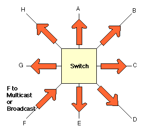
Many Ethernet switches handle multicast traffic as if were broadcast traffic. When a multicast packet reaches such a bridge/switch, it forwards the packet to all active interfaces, effectively flooding the network. This ensures all clients receive the multicast data, but has the drawback that every LAN segment carries all the multicast traffic, even when the directly connected clients do not require the data. This mitigates most of the advantages of switching when considering multicast traffic.

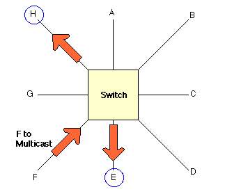
A bridge/switch can be designed to provide multicast support by implementing filters at the output ports of the device which remove the packets for which the clients attached to the ports have no registered interest. This operation resembles the processing for Virtual LANs (VLANs) and may be performed using the same/similar processing engine. Three approaches are possible when configuring this style of operation:

Some level of multicast filtering is highly desirable within a bridge/switch that needs to forward multicast traffic. These procedures allow a the device to selectively forward multicast packets only to hosts which register an interest in the corresponding multicast group address. Without the addition of such procedures, Level 2 bridges/switches are forced to broadcast multicast packets to all connected LANs. While manual configuration may suffice for applications such as multicast file transfer, or multicast distribution to network news/web cache clients. For the majority of multicast applications, one of the two dynamic schemes is recommended.
See also:
A page shows examples of various types of networking equipment, including Bridges and Switches for Ethernet.